2 wire control vs 3 wire control. 2 wire control and 3 wire control Motor starter diagram start stop wire phase wiring control three starting circuit 480v electrical reversing voltage holding electronic simple ac Circuit control wire three start diagram motor button auxiliary industrial push seal contacts coil ladder connected
Ladder Diagram Basics #3 (2 Wire & 3 Wire Motor Control Circuit) - YouTube
Wire control circuit systems circuits fluid power hydraulics pressbooks openoregon pub hydraulic electrical behavior describe Wire motor control diagram circuit ladder basics Auxiliary reversing voltage rockwell latching diagrams contactor eletrical ghisalba dol chapter switches
Circuits divided
Three-wire control circuit with indicator lampWiring diagram: chapter 1.1. full-voltage non-reversing 3-phase motors Stop start circuit jog control diagram motor configuration wire wiring two three jogging electrical motors operation gif november electricala2z sponsoredMotor button stop start diagram wiring starter circuit relay retain 480v control wire 120v push switch electrical symbol phase limit.
Wire two control circuit motor diagram three connected configuration motors controls turn only notLadder diagram basics #3 (2 wire & 3 wire motor control circuit) Plc circuit ladder electrical motor control relay phase robotics electronics program above threeTwo wire & three wire motor control circuit.

2 wire control circuit diagram. motor control basics. controlling three
Wire control vs3 wire motor control Wiring starter auxiliary reversing rockwell voltage latching diagrams contactor eletrical dol ghisalba connection volt industrial switchesMotor starter diagram. start stop 3 wire control. starting a three.
3 wire motor control circuitTwo wire & three wire motor control circuit Two wire & three wire motor control circuit6.7 2 and 3 wire control circuits for fluid power systems – hydraulics.

Motor diagram control wiring circuit wire motors phase basics controlling diagrams three switch sponsored links
Stop wiring controlsCircuit control wire lamp three indicator motor wiring diagram ladder starter coil industrial when fig above energized added show Wire circuit two control motor diagram three configuration gif electricalMotor diagram control stop start circuit wire sponsored links.
Electrical electronics robotics: plcClear electronic project box: wiring diagram for 3 phase motor Three-wire control circuit3 wire motor control.

Motor control circuit diagram / start stop 3 wire control
3-wire controlAuxiliary reversing rockwell voltage latching diagrams contactor electric eletrical dol ghisalba rotate viz switches volt .
.


Three-Wire Control Circuit with Indicator Lamp

Clear electronic project box: Wiring diagram for 3 phase motor

Two Wire & Three Wire Motor Control Circuit | Motor Control Circuit

3 Wire Motor Control Circuit

Electrical Electronics Robotics: PLC

3-Wire Control - Start Stop Circuit

Two Wire & Three Wire Motor Control Circuit | Motor Control Circuit
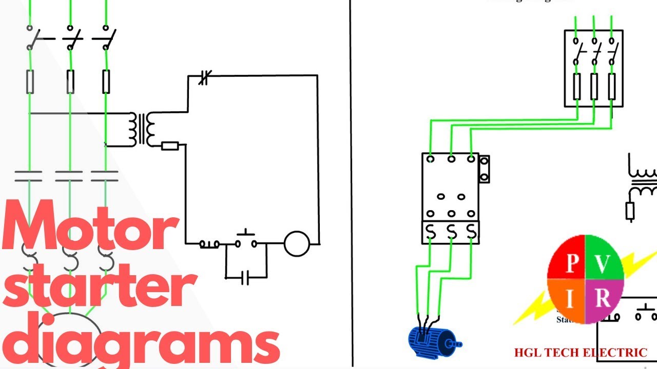
Motor Starter diagram. Start stop 3 wire control. Starting a three
